Ornithopter

projects

Flapping-wing flight is fascinating. It inhabits that intriguing space between biology and technology; simultaneously harking back to Da Vinci’s flying machines while also invoking vivid imagery from Dune and other imagined futures.   Although feasible with modern technology in very specific cases, it remains impractical:  the challenges of generating both lift and thrust with a flapping surface, as well the incredible mechanical complexity required makes it a technological dead-end.

When Maker Festival Toronto  put out a call for “spectacle”, I jumped at the excuse to build something impractical, but visually satisfying. The festival has been held in the Toronto Public Library for the past few years now, which provides a vast vertical space. With thousands of people milling below, a large ornithopter was clearly the right thing to do. Not one that actually flew, because that would require power and danger and engineering far exceeding the scope of a spare-time project, but rather a kinetic sculpture, gently flapping above the crowds.

IMG_20160710_094829b


Perusal of the internet brings up a lot of micro ornithopters, a small, but lively community, and of course this majestic human-powered ornithopter by UTIAS. My all-time favourite ornithopter is DelFly, from the highly capable folks at TU Delft.

From this survey it seems that getting something small to fly is relatively easy, but as the aircraft becomes larger, flapping becomes a harder problem. The success of small ornithopters can be ascribed to the favourable weight to power ratio, and that the scale of the wing membranes gives a good balance between structure and flexibility, which seems to result in wing curvature that gives us lift.

I wanted a device that is light enough to easily and safely suspend above people, flaps in a pleasing way, and can be powered with a small motor and battery. So, let’s build it.

The wings

It’s all about the wings.  For a previous project, where I algorithmically optimised a Jansen walker, I spent a lot of time building simulations of mechanical linkages. It was fairly easy to build a similar implementation for the wing mechanism. This allows me to specify a linkage design, simulate the movement using a physics engine, and measure the key parameters that I’m interested in. Of course, the simulation is not perfect, but it gives me a quick way to explore different linkages. In this case I was specifically interested in minimising the torque required, and plotting the wing tip to evaluate movement.


wing_coords

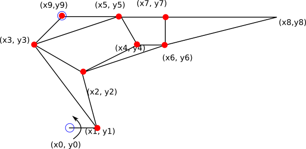
The linkage mechanism. The blue points are anchored to the body of the ornithopter, red parts are pivot joints. The entire linkage is driven by rotating the bar 0-1 around point 0. I measure the torque at point 0 – the lower this is, the less likely the motor will stall.  To limit the scale of the problem and flatten the wing profile, I constrained points 3, 9 and 5, as well as 2, 4 and 6 to be in a straight line.

screen

After several iterations and a bit of tweaking, I settled on this. The wing is pulled in about 15% on the upstroke, before reaching out to maximise area on the downstroke. I took the dimensions of the bars into Inkscape and drew the shapes I wanted. These were then  printed out, traced, and one after another cut from 3mm aircraft plywood using a scroll saw.

The links are joined together with M3 machine screws. To increase rigidity of the mechanism, I doubled up the top bar (3-9-5), using 20mm nylon stand-offs to keep things nicely aligned and low friction. The wing tips were made by attaching thin balsa strips to the end of the linkage.

The wing membrane was cut from nylon kite fabric. This may be a bit stiff for my application: it might be worth substituting a lighter fabric.

Body

The body provides the structure for attaching the wings, motors and tail to each other. The main parts are made from 12mm x 12mm balsa strips, with all joints reinforced with either struts, corner triangles, or braced on either side with bits of plywood.

The tail is also constructed from two balsa strips, mounted in a V, and at an angle to the main body. This serves to balance and stabilise the assembly. The inner edges of the wings were glued to the top of the frame, while leaving sufficient space to allow for movement.

A piece of kite line (45kg braided dacron) was attached to the front and back of the top of the frame, to form a two-legged bridle. The main suspension line was attached to the bridle with a Prusik knot, to allow pitch adjustment, and a swivel, to prevent twisting in the line. I highly recommend Prusik knots.

IMG_20160710_165326b

Actuation

Each wing is independently driven by a 65:1 geared 6V motor. These are directly connected to the driving arm, with the motors mounted on a piece of aircraft plywood. Experimentation showed that they will run happily (if a bit slow) down to 3V, drawing about 250mA on average. A 2400mA LiPo battery gave me enough power to survive a 10 hour day.

However, the wings have different torque requirements, due to variations in wing size, varying friction on the joints, and external things happening to the device. I therefore used two large gears at the front to keep the flapping synchronised. There is no significant force transferred between the gears; they only couple the movement of the wings together. A balsa wood guide helps to keep the gears engaged, despite some warping in the plywood.

Conclusion

In the end, the ornithopter weighed 950g, had a wing span of 2.5m and a length of 3m. About a quarter of the weight was due to the motors and battery, with the synchronisation gears also playing a significant part. The torque required for movement is low enough that a single motor would have sufficed, but this would have complicated the gear arrangement.

IMG_20160709_104707

It was suspended from the balcony of the third floor of the library, down to just above the first floor, flapping above an origami forest and Epilog lasermen.    I merely had to walkaround all day, checking that it stays in place.


My main criticism of the build is the excessive flex in the wing assembly. As the wing moved, force on the wing membrane would pull the moving part of the linkage back, causing the fabric to drag behind the stroke. A stiffer mechanism would significantly increase the thrust – perhaps by adding a parallel linkage 300mm behind the first?


Various people and organisations contributed to all of this happening:

Design files for the flapping mechanism are available here.

Backyard glass blowing

projects
This one is legitimately dangerous.  Do not try at home.  Glass is an amazing substance, but I recommend finding a studio where you can work on it.

A couple of years ago*, in the time of great projects, before visas, work and life got in the way, we tried our collective hand at glass blowing.  Why? Because high temperature physics makes for lots of trial and error, and great fun.  Also,  it fits into my theme of trying to recreate old technologies.  But mostly to see if we could.

It started with a not uncommon problem: we had accumulated so much glass for recycling that actually getting it to the recycling centre became a logistical challenge.  Add some gin, and a bit of youtube, and we became convinced that we (Rob, Khilan, I) had a great opportunity at hand.  But first there was much to learn.

Some physics

Most container glass is soda-lime glass, which consists of approximately 75% silicon dioxide (silica), sodium carbonate (soda), lime and smaller amounts of other minerals.  The silica comes from sand; this is fired with the other minerals at up 1675 degrees Celsius to fuse.  The composition of ingredients determine the physical properties of the resulting glass:  colour, softening temperature, chemical durability, and hardness (to some extent).  This is a very energy-intensive process, luckily the resulting glass can easily be recycled by heating it and reshaping it.  “Easily” still requires temperatures near 1000 degrees, however.

Glass-blowing, as it should be done

A simplified view of the standard glass-blowing process looks as follows:  a crucible is filled with glass, this is gently heated.   (Real professionals might start with raw materials, to precisely control the composition.) Between 500 and 800 degrees the glass softens, and slumps together. As the temperature is further increased, the viscosity decreases, and around 1100 degrees, it is right for blowing – imagine the viscosity of honey, and you’re close enough.   A long tube, the blow pipe, is inserted into the molten mass of glass, and a small amount picked up: the “gather“.   To prevent the glass from sagging to one side, the blow pipe is constantly rotated.   The gather is initially shaped into an even form by rolling it on a steel plate (marvering).

The glass blower then proceeds to inflate the vessel by puffing small amounts of air into the pipe.   As the glass is very hot, it heats the air in the middle. As this air expands, it pushes the glass out further.  So it is very different from inflating a balloon.  Here a beautiful negative feedback loop comes into play:  as the glass thins in one part, it cools faster, increasing the viscosity in that area.  Further expansion will therefore happen in the thicker areas.  As a result, we can form vessels with even wall thickness without any internal support  (which we would require when a technology such wheel-throwing ceramics would require).

When the wall gets too thin, more molten glass is gathered, and the expansion continued.  The blown vessel can be shaped with various tools while still hot – the viscosity slowly increases as it cools down.  If the glass cools down too much, it is reheated in a very hot oven  (~1400 degrees): the joyfully labelled “glory hole”.

When the vessel is complete, the bottom is attached to a new rod, called the punty.  A small blob of molten glass is gathered on the punty, and stuck onto the base of the vessel.  The top attachment can then be grooved and snapped off.    This allows finishing of the top of the vessel, to shape and polish the neck and rim, for example.  Once the top is finished, the punty attachment is also removed.

Once complete, the vessel needs to cool down very slowly to prevent the thermal stresses from fracturing it.  This annealing phase happens between 380 and 480 degrees, over several hours to days.

DIY glass-blowing

Nowadays, all of the above is done using gas furnaces, temperature control, and modern materials, but the Romans were blowing glass more than 2000 years ago without any of that.  This forms the basis of our approach: do it like it’s 100 BC, with some applicable short-cuts, and more accessible knowledge on our side.   Needless to say, we adjusted our definition of success accordingly.

The first major challenge we had to overcome, was getting a furnace to be hot enough.  To estimate temperatures, we looked at the colour of the hottest part of the furnace: we really needed a white colour to ensure the glass got hot enough.  This requires three things: fuel, oxygen, and insulation.   Insulation was easy – we bought a high-temperature ceramic blanket, as is used in kilns.  A “salon tested” hair dryer acted as bellows, to provide the oxygen.   For fuel we started on charcoal, but soon upgraded to house coal, because it has a higher energy density, which means more heat.

A stainless steel tube served made a good blow pipe – the thermal conduction is low enough that you can hold one end while the other is placed at a crazy temperature.  As we couldn’t source an affordable ceramic crucible in time, we simply used a cheap stainless steel saucepan.

As a first try, we constructed a small furnace from bricks in the garden.  We lined the inside with ceramic wool, and filled the spaces between bricks with building sand.  The space inside was split in half, with a shelf for the crucible in front, and space for the coal at the back.

This heated up really quickly, due to the low thermal mass of the system.   Also, that much fire in a confined space is more exciting that anticipated:  it rumbles like a frustrated rocket, it wants to push out and escape.  The pressure of the fire burning in such a small space is very noticeable. And the radiated heat is intense!

And our pesto jars gradually turned into a crucible of molten glass.  Not just slumping, but quite liquid.  Still not quite soft enough to gather and blow, but close.

7319641838_77ae82a5bd_o

However, the ceramic wool isn’t really meant to be used like this – all the poking and fiddling around it at high temperatures caused it to disintegrate.  And then the rather angry fire leaked though the bricks,  with jets of flames reaching 50cm out,  and shutting us down for the rest of the night.

7319564682_0556cf3025_o

The second iteration

Although not successful on the first round, we learned many things.   We needed to lift the crucible to be heated from below, not the side, for better heat distribution.  So we constructed a steel grid to put the saucepan on.  The door needed a redesign, so we put more steel in there as well.  And the furnace itself was adapted to have a layer of bricks on the inside of the insulation as well.  In addition the mechanical protection this provides, the bricks increased the thermal mass of the inside which helps keep the temperature more stable.

7361211734_cd070332ed_o

The heavier construction meant it took much longer to get the furnace up to temperature.  This time we encountered new issues: The extended exposure to very high temperatures did not play well with the metal in the furnace.  For example, the steel grid disappeared completely.  The stainless steel crucible became less stainless, slowly oxidising in the heat.   Things are very different at 1000 degrees.

We were also emitting a lot more smoke, primarily due to not getting enough oxygen into the furnace to satisfy the fuel.  At this point I suddenly understood what the industrial revolution must have felt like:  we smelled of smoke, we coughing up soot, and everything was dirty.   Needless to say, the neighbours were not amused.

Again, a couple of gathers happened, but we couldn’t get beyond the marvering stage.

The third iteration

Finally, we admitted defeat on the fuel front.  We just couldn’t get clean enough glass and sufficiently well-distributed heat from the coal.  One friend provided his propane cylinder, another brought his kiln for annealing –  a problem we had not considered at all yet.   It pays to have the right friends.

This worked quite well.  With a team of suitably protected volunteers, we melted a pot of glass and tried to blow some.  One person would manage the door to the furnace, protected with goggles and welding gloves – this was a taxing place to be.  Blowing was a specially choreographed dance:  The door would be opened, and the blow pipe be inserted for the first gather.  Wait for the pipe to start glowing yellow-white, then gently dip into the crucible.  Pipe out, door closed, marver, keep spinning, a gentle puff, cap the pipe with your thumb to let the air expand.   If you blow too much, you’d simply burst a bubble of glass, spraying thin shards everywhere.  Sometimes, the viscosity would by just right, the blower would stay calm, and we’d get a gentle inflation from the glass, at that point glowing bright orange.  Door open, reheat, gather some more, spin, retreat, close door.  Spin the pipe, blow again.  Now for detachment:  roll the vessel along a stand while someone tries to shape a groove into the neck with shears.  Then attempt a thermal stress fracture by carefully dripping some cold water on the groove.  At this point, the doorman would be present again, to catch the still hotter than 500 degrees glass in his gloves, for transfer to the annealing kiln.  The still hot blowpipe can then be quenched in a bucket of cold water, accompanied by dramatic spitting and steaming.  If you’re lucky this would crack the remaining glass off the pipe, cleaning it for the next round.  And repeat.

However, after 2 hours of direct heating, the crucible would burn through, causing a lava-like flow of molten glass to flow out, usually directly at the gas flame.   This would require swapping out the crucible, and starting with fresh pots, and new pesto jars.  One of the crucibles was made of steel, but not stainless.  All the (clear) glass melted in this pot came out green, due to the iron oxides contributed by the steel.

But did it work?  Well, we managed a couple of mediaeval looking hollow glass baubles.  Not something that I’d put in my mouth, and not particularly fine and crafted,  but they are definitely made of blown and spun glass.


It is a decidedly non-trivial process. (And if you made it this far, you will enjoy this video.)


* I’ve just counted: four.  Still, the world deserves to know about this. Also, many words.

Yarn swift

projects

(originally posted on Thingiverse, moved here for greater coherency and minor updates.)

A swift holds a hank of yarn while it is being wound into a ball, so you don’t have to fight it all the way.
If you’re a hardcore knitter, you buy your yarn from hippy communes in faraway places, or you spin it yourself[1]. This gives you yarn in hanks – long loops that are good for dyeing, but non-trivial to knit with. To get it into a ball, you need someone or something to hold it and prevent tangles, while you do the winding by hand or with a ball winder. That’s where the swift comes in: it holds the yarn, and rotates gently on demand, allowing to you to unwind/rewind yarn as needed without requiring a large family to assist you.
The canonical example of a swift is the umbrella swift.

Umbrella swift (wikipedia)

Umbrella swift (wikipedia)

We[2] wanted something similarly light, yet sturdy enough for the wildest of knitting parties.  After extensive tea, we converged on a design that uses scissoring arms to expand and contract.  A bit of CAD and lasers later, we had this:

No load.

No load.

Three arms are mounted on a spindle that rotates around a threaded rod. It can rotate freely, but has sufficient dampening to not overshoot – it just feeds you yarn on demand.  Cable ties make good hinges, apparently.

6370967383_61482c5bba_o

Loaded.

The arms of the swift expand to the diameter required for the skein when you press the top disk downwards, to at least 1.8m, for our design.

And it spins:

Design files and instructions are available on Thingiverse.
[1] Disclaimer: we are not knitters, this is merely an observation.
[2] Rob

Van Leeuwenhoek Microscope

projects

In Leiden I stumbled across a Antonie van Leeuwenhoek microscope[1]. If your early microbiology and microscopy is a bit rusty, I would highly encourage you to go on an all night research binge – it is exciting stuff!  Also, when near Leiden, visit Museum Boerhaave.  For science!

Simple Van Leeuwenhoek microscope, Museum Boerhaave

Simple Van Leeuwenhoek microscope, Museum Boerhaave

I wanted that microscope. Not just to have, but to make one. To get close to the materials, to better understand the process. Also, after a few years of consistently thinking about abstract algorithms, making something physical was extremely appealing. And the proximity to great science was appealing: I can now say that, just like Robert Hooke, I recreated a very satisfying little microscope.

The microscope uses a glass bead as lens; this is housed in a brass body, with adjustment screws for adjusting the focus an object position. I largely follow the instructions here [2], which was particularly useful for the lens making process. I’m new to both glass and brass, which made this extra fun.

I tried a number of glass sources, but ISO standard pesto jars performed very well. You need a fairly low melting temperature, and limited stress in the glass. I used drawing to make the lenses, apparently grinding and blowing are also options[3]. For someone with limited tools and glass experience, I highly recommend drawing. A fairly hot flame is required, but it needn’t be huge. An alcohol burner failed, but a cheap pencil torch worked for me. More heat will give you larger beads, with a better (longer) focal distance, but they also have more imperfections and lower magnification.

Desk.  Wear eye protection.

Wear eye protection.

To make the beads, melt the tips of two shards in the flame, then smoosh them together to form a glob of glowing glass. Based on colour, I would estimate it to be around 700-800’C. Remove the ball from the flame, the gently draw the two shards apart. A thin glass fibre should form, with the thickness determined by the temperature of the glass and speed of drawing. Collect several fibres.

To make the lenses, you melt the tips of the fibres in a hot flame, one at a time. As the strand melts, the surface tension pulls the molten glass into a little ball. This little sphere will act as a high magnification lens. Gently rolling the fibre between your fingers encourages even heat distribution, and better bead formation. As the ball grows, the glass fibre bends down, pulling more of it into the flame. At some point the fibre will burn through, resulting in an upper limit of the size of bead. My 2 – 3 mm diameter beads came out best – very round, clear, with limited imperfections.

6832952373_54bfa67745_o

Lens beads – the large one wasn’t amazing, but the small ones did quite well.

Dimension were collected from a number of sites, but I mostly stuck to those here[2].  The body sheets are cut from a 0.5mm brass sheet.  The lens cavity is made by squeezing a sacrificial lens bead between the body sheets, and gently beating them together between two bits of wood.  This process bends out the sheet around the part where the lens will be. Due to the short focal distance of the lenses, one also needs to grind down the excess brass that the lens displaced – all you need is a thin lip to keep the final lens in place. Once everything looks nice and solid, insert the bead you’d like to use as lens, then rivet the two sheets together to keep everything snug and stable. I used more of the 2mm rod for the rivets.

6782609274_97e6943337_o

Test fitting the lens.

The L-bracket is cut from 1mm stock.  The focus block is about 5mm thick. I tapped 2mm holes in where directed. For the screws, I used a die to cut thread into a 2mm rod. This can take a while.  A bit of hammering gave wings of the screws.

All the bits

All the little bits.  The body is about 50mm x 25mm, screws were all cut from 2mm rod.

6782695264_e7d194c54f_o

The focus assembly.  The long rod rotates freely in the focus block, while the threaded hole in the L-bracket determines vertical displacement.

Then assemble. A sharpened screw acts as holder for the object of inspection. If you can’t impale the object of your curiosity, wax or (in my case) a dab of glue helps to keep the object in place.

6928888183_c6fb245260_o
Hold the microscope close to your eye, against the light – blue sky is good, some people use the sun. Then twiddle and twist screws to get everything into focus. The long rod controls the up-down displacement of the object, while the short screw in the image above pushes the focus block away from the body sheet, lifting the object with it.  The L-bracket can rotate, which gives a combined left-right and up down movement.

Taking a photo through the lens requires at least a 4 opposable thumbs, but here’s a shot of a hair.

Science!

Science!

Future project: the Aalkijker (elver viewer) – a small glass tube to contain the transparent specimen, with lens and screws as above.

Resources:

[1] http://www.museumboerhaave.nl/object/enkelvoudige-microscoop-v07017/
[2] http://www.mindspring.com/~alshinn/Leeuwenhoekplans.html
[3] http://lensonleeuwenhoek.net/content/tiny-lenses
[4] http://www.microscopy-uk.org.uk/mag/artjul07/hl-loncke2.html